FER/PrePost
processor
The objective of developing FER/PrePost is to facilitate the development of
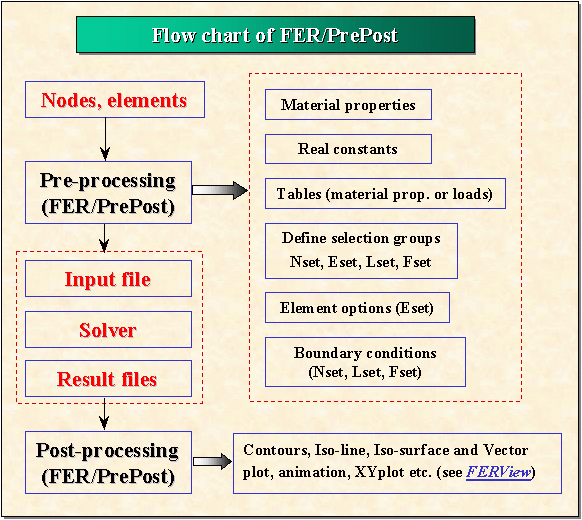
finite element analysis software. The following figure represents the flow chart
of FER/PrePost in which two interfaces are developed :
- CAD to FER/PrePost
: Because this Pre/Post processor imports only nodes and elements, you
can use any CAD software to create your geometric model.
- FER/PrePost to solver
: Because all necessary information has been obtained in the pre
processor, it is very easy to write the input file for your solver with
any format that you want. All you need to do is to prepare the
geometric file
(nodes and elements) and to define the input file format
(or the name of your solver which can be called directly by FER/PrePost)
as well as the result file format for post processing.
The main capabilities of FER/PrePost 1.0 include :
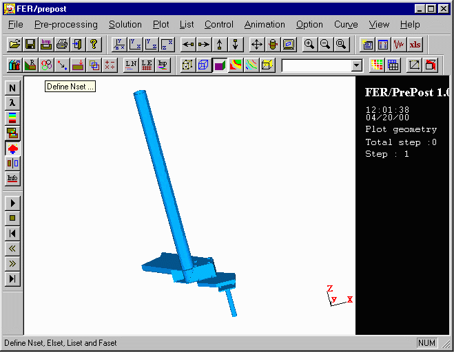
- Friendly graphical user interface (Figure 1),
- Import nodes and elements from any CAD software (ProEngineer, I-DEAS
etc),
- Have
different plotting methods for surface or volume nodes,
elements,
- Input material properties, real constants, solution control parameters
etc. with a dialog box,
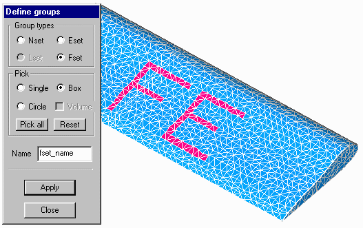
- Select nodes, line segments, surface elements, and volume element
groups in a flexible way (Figure 2),
- Choose element attributes and apply boundary conditions using the
selected groups,
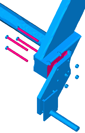
- Modify the node coordinates of selected node groups. It is very
effective for applying boundary conditions for some complex structures
(Figure 3),
- List
nodes, elements, materials, etc,
- Give
an input file in the format you need,
- Have
all postprocessing capabilities of the post-processor FERView, in
addition, it includes modal shape plotting (Figure 4).
Figure
1. Graphical user interface of pre/post processor FER/PrePost 1.0
Figure
2. Very easy operations for defining nset, eset, lset and fset.
 __
__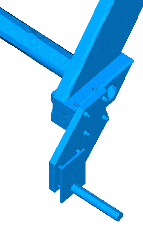
Figure
3. Applying boundary conditions and assembling the structures
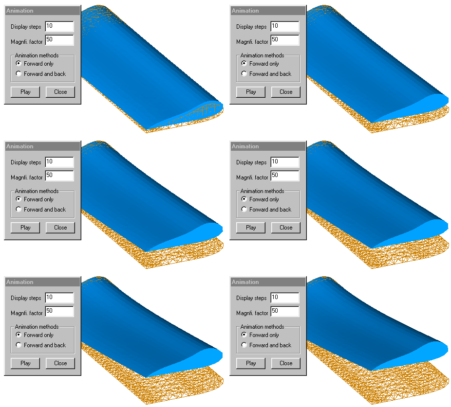
Figure
4. Modal shape plotting (Modal analysis for airplane wing: first
mode)